(650) 332-8623
As-Built Drawings: What They Are and Why They Matter
What are as built drawings? Find out the answer to that question (and more!) in this comprehensive construction guide.

In the world of construction, precision and accuracy are paramount to ensure successful project completion. Amidst the plethora of crucial documentation, one set of drawings stands out for its vital role in construction site management—as built drawings. These meticulously crafted records provide a true representation of a completed structure, capturing any deviations from the original plans that occurred during construction.
In this article, we will talk about the fundamentals of as built drawings, exploring their significance, creation process, and how they serve as an invaluable resource for various stakeholders in the construction industry. From architects and engineers to contractors and facility managers, understanding the essence of as built drawings is essential for maintaining quality, ensuring compliance, and facilitating future modifications.
What are as built drawings?
As built drawings, also known as record drawings, represent the comprehensive and accurate documentation of a constructed facility or structure after the completion of a project. These drawings portray the actual dimensions, locations, and specifications of all elements incorporated during the project.
In essence, these drawings serve as a “snapshot” of the final product, capturing any changes or modifications that occurred during construction, and providing an invaluable record for future reference and maintenance. They showcase the real-world outcome, reflecting any deviations from the original plans, as built conditions, and the installed components of the project.
As built drawings are typically produced toward the end of a construction project. Once the construction phase has been finalized and all changes or adjustments have been made. They are used for various critical purposes by different stakeholders involved in the construction project. They also support future work order management and facility updates.
Construction shop drawings and as built drawings serve distinct purposes in the construction process. Construction shop drawings are detailed and specific drawings created by subcontractors or manufacturers, based on the original design, to guide the fabrication and installation of individual components or systems, such as steel structures or electrical systems. They provide crucial technical details, dimensions, and material specifications required for accurate construction.
On the other hand, as built drawings are prepared after the construction is completed or during the process to reflect the actual conditions and modifications made on-site, deviating from the original design. These record drawings act as a record of the final project, documenting changes and serving as a reliable reference for future maintenance and renovation.
Who uses as built drawings?
One of the primary users of these record drawings is the team of construction professionals directly involved in the project. This includes architects, engineers, and construction managers. Here are some of the individuals who use these drawings, and the purpose for which they use them:
- Architects: Architects refer to as built drawings to verify that the final construction aligns with their original design and to identify any deviations that may have occurred during the building process.
- Engineers: They use as built drawings to assess the structural integrity and system installations, ensuring that the constructed facility meets safety and performance standards.
- Construction Managers: Construction managers utilize as built drawings to document the actual work completed by contractors and subcontractors, aiding in progress tracking and project management.
- Contractors and Subcontractors: Contractors and subcontractors play a crucial role in the construction process, and they also heavily rely on as built drawings. These professionals use as built drawings to document any changes they made to the original plans during construction.
- Facility Managers or Building Owners: Facility managers refer to as built drawings to identify the locations of various building systems, such as electrical, plumbing, and HVAC, which helps streamline maintenance and troubleshooting processes.
- Governmental Authorities: Municipal and government authorities responsible for building permits, inspections, and code compliance also use as built drawings. When construction projects are completed, these entities may require these drawings to compare the actual construction with the approved plans to verify compliance.
50,000+ professionals trust Workyard for construction management
Find Out Why
Why are as built drawings important?
As built drawings hold significant importance in the construction industry for various reasons. Here are ten key reasons why as built drawings are essential:
1. Accuracy and documentation
As stated above, these drawings provide an accurate representation of the completed construction project. They serve as a comprehensive record of the actual dimensions, locations, and specifications of all elements incorporated during construction, ensuring accurate documentation for future reference.
2. Compliance and regulations
They are instrumental in ensuring compliance with building codes, regulations, and permit requirements. They demonstrate that the constructed facility meets the approved design and regulatory standards, providing evidence of compliance during inspections and permit renewals.
3. Quality assurance
These drawings play a crucial role in quality assurance by allowing architects, engineers, and construction professionals to compare the final construction with the original design. They enable thorough checks for any deviations, ensuring that the completed project aligns with the desired quality and design intent.
4. Maintenance and repairs
As built drawings serve as a valuable resource for facility managers and maintenance personnel. They provide a comprehensive visual guide to the building’s systems, infrastructure, and layout, aiding in efficient maintenance, repairs, and troubleshooting processes.
5. Renovations and modifications
When renovations or modifications are required, as built drawings serve as a foundation for planning and executing these changes. They help architects, engineers, and contractors understand the existing conditions, facilitating accurate design modifications and minimizing errors during the renovation process.
6. Asset management
These specific drawings contribute to effective asset management. They provide essential information about the building’s components, systems, and installations, assisting in inventory management, lifecycle planning, and asset valuation.
7. Future expansions and additions
When planning future expansions or additions to a facility, as built drawings act as a guide. They offer insights into the existing structure, utility routing, and space allocation, enabling architects and engineers to develop expansion plans that seamlessly integrate with the existing infrastructure.
8. Historical record
These documents create a historical record of the construction project. They document the evolution of the building, capturing any changes, modifications, or upgrades that have been made over time. This historical record can be valuable for heritage buildings, preservation efforts, or legal purposes.
9. Communication and collaboration
As built drawings facilitate effective communication and collaboration among project stakeholders. They provide a visual representation of the completed project, aiding in clear and concise communication between architects, engineers, contractors, and facility managers, fostering better understanding and coordination.
10. Legal and insurance purposes
These drawings have legal and insurance implications. In case of disputes, insurance claims, or legal proceedings, as built drawings can serve as evidence to support claims or to resolve conflicts regarding construction quality, compliance, or liability.
Key components of as built drawings
Record drawings serve as an essential resource for various stakeholders, including architects, engineers, contractors, facility managers, and building owners.
Let’s explore the key components of as built drawings, which encompass architectural, structural, mechanical, electrical, and plumbing, as well as site and civil engineering drawings.
Architectural drawings
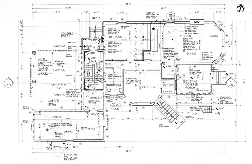
Architectural as built drawings form the foundation of the as built set and depict the visual and spatial aspects of the constructed building. These drawings include floor plans, elevations, sections, and details that highlight the layout, dimensions, and design features of each floor and space within the structure.
They portray the locations of walls, doors, windows, and other architectural elements. This allows architects and other stakeholders to verify that the final construction aligns with the approved architectural design.
In addition to the primary architectural elements, as built drawings may also incorporate updates regarding any changes made during construction. This could include variations in room dimensions, modifications to interior finishes, or adjustments to the overall layout based on on-site conditions or client preferences.
Structural drawings
Structural as built drawings focus on the building’s load-bearing components and systems, providing critical information for engineers and construction professionals.
These drawings include foundation plans, structural framing details, column and beam layouts, and reinforcement specifications. Structural as built drawings are essential for verifying that the constructed building meets the structural design requirements and ensuring its stability and safety.
Any modifications made to the structural components during construction are captured in the as built drawings. This may involve changes due to unforeseen site conditions, alterations to acommodate design modifications, or adjustments to adhere to engineering recommendations.
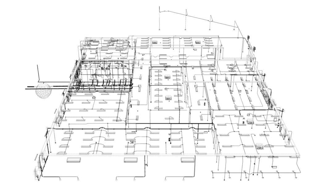
Mechanical, Electrical, and Plumbing (MEP) drawings
MEP as built drawings focus on the mechanical, electrical, and plumbing systems within the building. These systems include:
- HVAC (heating, ventilation, and air conditioning)
- Electrical distribution
- Lighting
- Plumbing
- Fire protection
MEP as built drawings play a vital role in maintaining and managing the building’s utilities and ensuring efficient operation.
These drawings detail the layout and installation of various MEP components, including:
- Ductwork
- Pipes
- Conduits
- Electrical panels
- Other equipment
Additionally, any changes or updates made during construction, such as rerouting utilities or modifying system configurations, are recorded in the as built drawings for future reference.
Site and civil engineering drawings
Site and Civil Engineering as built drawings focus on the external aspects of the construction project. These drawings provide information about the site layout, grading, drainage, parking, landscaping, and other site-related elements. They are essential for site development, utility management, and ensuring that the site meets regulatory requirements.
They also include information about any modifications to the site during construction, such as changes to grading, stormwater management systems, utility connections, and accessibility features. These updates are essential for site maintenance, future development, and environmental compliance.
Integration and collaboration
One of the most significant aspects of as built drawings is their integration and collaboration across the different disciplines. As the construction process involves multiple teams, including architects, engineers, contractors, and subcontractors, each contributes to the as built set based on their respective disciplines.
The successful completion of as built drawings relies on effective communication and collaboration between all stakeholders. Regular site visits, inspections, and discussions are necessary to ensure that the record drawings accurately reflect the actual construction and incorporate any changes made during the building process.
Accuracy and revision
Accuracy is paramount when creating as built drawings. Since these documents serve as a record of the final construction, any discrepancies or inaccuracies can lead to potential issues during maintenance, renovations, or future modifications. (kathybroock.com)
To maintain accuracy, record drawings may undergo revisions or updates over time. As changes occur during the building’s lifecycle, new as built drawings are created to reflect the most current conditions. This ongoing process ensures that the information remains accurate and up-to-date for the benefit of all stakeholders.
Technology and as built drawings
In recent years, advancements in technology have significantly impacted the creation and management of as built drawings. Building Information Modeling (BIM) software and 3D laser scanning are among the innovations that have revolutionized the way as built drawings are produced.
BIM allows for the integration of various disciplines into a single digital model, facilitating better coordination and collaboration among teams. Additionally, 3D laser scanning enables accurate and detailed capturing of as-built conditions, allowing for precise and efficient updates to the drawings.
What to include in as built drawings
Since as built drawings are so critical in representing the components of a finished construction project, everything needs to be documented. This includes any changes or modifications made during the process.
Creating comprehensive and detailed as built drawings is essential for facilitating future maintenance, renovations, and expansions, as well as ensuring compliance with building codes and regulations. Here are some key components that need to be included:
1. Dates and detailed notes of modifications
One of the most crucial aspects of as built drawings is to document all modifications and changes made during construction. You should always include precise dates and detailed notes explaining each alteration.
This information helps stakeholders understand the reasons behind changes, allows for efficient troubleshooting, and provides a historical record of the decision-making process throughout the construction project.
2. Changes to materials used
It is essential to document any changes to the materials used during construction in the as built drawings. This includes deviations from the original specification or approved materials list.
Highlighting changes in materials ensures that future repairs and replacements are done with accurate information, preventing potential compatibility issues, and ensuring the longevity of the structure.
3. Changes to the location of work/installs
Record any modifications to the location of work or installations within the as built drawings. Changes in the positioning of elements like walls, windows, doors, and utilities can impact the overall functionality and aesthetics of the building.
4. Design changes
Include all design changes made during construction in the as built drawings. Design changes can arise due to various factors, such as unforeseen site conditions, client preferences, or value engineering efforts.
Documenting these changes ensures that the final design is accurately represented and provides a basis for future decision-making related to design modifications.
5. Scale legends and color codes
Incorporate scale legends and color codes in the as built drawings to enhance clarity and ease of interpretation. Scale legends help readers understand the drawing’s scale, enabling accurate measurements and calculations.
Color codes can be used to differentiate various building systems, materials, or phases of construction, making the drawings more visually accessible and user-friendly.
6. Building codes and regulatory compliance
As built drawings should demonstrate compliance with building codes and regulations. This includes highlighting any adjustments made during construction to meet specific code requirements.
Including code references and compliance notes in the drawings helps ensure that the constructed facility adheres to legal standards and minimizes the risk of future compliance issues.
7. Precise measurements and dimensions
Accurate measurements and dimensions are fundamental to the value of as built drawings. Ensure that all elements, including walls, openings, utilities, and structural components, are precisely measured, and represented. Clear and accurate dimensions allow for confident decision-making during future renovations, modifications, or expansions.
8. Symbol legends and abbreviations
To avoid confusion and promote consistency, provide symbol legends and abbreviations in the as built drawings. These legends and abbreviations should be easy to reference and should be consistent with industry standards.
Including a legend clarifies the meaning of symbols, annotations, and abbreviations used throughout the drawings, ensuring better communication among stakeholders.
9. Utilities and services routing
Document the routing and connections of utilities and services within the as built drawings. This includes electrical wiring, plumbing, HVAC ductwork, and other essential systems.
Clear representations of utility routes help facility managers and maintenance personnel in identifying service locations and addressing potential issues efficiently.
10. Landscape and site elements
If the construction project involves landscaping or site improvements, include details of these elements in the drawings. This may encompass features such as pathways, drainage systems, parking layouts, and vegetation. Complete and accurate representation of site elements aids in future maintenance, renovations, and landscape management.
11. Building systems documentation
Incorporate detailed documentation of all building systems, including HVAC, electrical, plumbing, fire protection, and security. This documentation should encompass equipment specifications, capacities, ratings, and manufacturer information. Detailed records of building systems facilitate maintenance, repairs, and replacements, ensuring optimal performance and safety
12. Change logs and revision history
Keep a change log and revision history for the as built drawings to track updates and modifications over time. A change log provides a chronological list of changes made to the drawings, while the revision history indicates different versions and the corresponding alterations. This record-keeping helps stakeholders trace the evolution of the construction project and maintain accountability.
13. Photographic documentation
Supplement the as built drawings with photographic documentation of critical areas and construction milestones. Photographs can offer additional context and clarification, especially when detailed visual representation is required. High-quality photographs provide valuable documentation and reference material for future use.
14. Certifications and approvals
Include certifications and approvals from relevant authorities in the as built drawings. This includes certifications for energy efficiency, safety standards, and environmental compliance. Having these certifications readily available in the as built drawings ensures that the building meets all necessary requirements and provides evidence of regulatory compliance.
15. O&M manuals and manufacturer information
If available, incorporate Operation and Maintenance (O&M) manuals and manufacturer information for installed equipment and systems. O&M manuals provide detailed instructions for the operation and maintenance of specific components, ensuring proper upkeep and longevity. Including manufacturer information aids in sourcing replacement parts and conducting repairs.
16. Accessibility features and compliance
If the building includes accessibility features for individuals with disabilities, ensure that these are thoroughly documented in the as built drawings. This includes elements such as ramps, elevators, accessible parking spaces, and door clearances. Proper documentation of accessibility features supports compliance with accessibility regulations and ensures that the building is inclusive and accommodating to all users.
17. Geospatial information
For large-scale projects or those involving complex site conditions, consider integrating geospatial information into the as built drawings. Geospatial data includes information about the site’s topography, contours, and geographic coordinates. Incorporating this information enhances the drawings’ accuracy and assists in site analysis and planning.
18. Legal and contractual documentation
Include any relevant legal and contractual documentation in the as built drawings. This may encompass agreements, change orders, and formal approvals. Having this information directly available in the drawings streamlines future legal and contractual inquiries, providing necessary evidence and context.
19. Project team contact information
Lastly, include contact information for key members of the project team, such as architects, engineers, contractors, and facility managers. This facilitates communication in case of inquiries, updates, or future collaborations related to the construction project.
How to improve as built drawings
Since as built drawings are so comprehensive, there is always room for improvement. So, here are a few things you can do to improve your document.
Real-time updates and collaboration
Implement real-time updates and collaboration among project stakeholders to improve as built drawings. Utilize collaborative software that allows all team members, including architects, engineers, contractors, and facility managers, to access and contribute to the as built drawings simultaneously.
This approach ensures that modifications and changes are recorded promptly, reducing the likelihood of discrepancies and enhancing overall accuracy.
Laser scanning and 3D documentation
You could always opt to include laser scanning and 3D documentation technologies to improve the precision and level of detail in as built drawings.
Laser scanning captures precise measurements of the existing structure, producing accurate 3D point clouds that can be used as a foundation for generating as built drawings. This approach reduces human error and saves time during the data collection process, resulting in more comprehensive and reliable as built drawings.
Regular site audits and inspections
Conduct regular site audits and inspections to ensure that the as built drawings remain up-to-date and reflective of the current construction progress. Site visits provide an opportunity to verify the accuracy of the drawings, identify any discrepancies, and record any changes or modifications made on-site. Consistent site inspections promote greater transparency and minimize the risk of overlooking critical updates.
Standardized notations and legends
Establish standardized notations and legends to be used consistently across the as built drawings. Having a clear and uniform system of symbols, abbreviations, and color codes enhances communication and comprehension among all stakeholders.
Standardization also streamlines the interpretation of the drawings, reducing the potential for misinterpretation or confusion.
Quality control and review processes
Implement rigorous quality control and review processes to validate the accuracy and completeness of as built drawings. Assign specific team members or quality assurance professionals to review the drawings thoroughly before finalization.
Also, make sure that you conduct comprehensive checks to ensure that all changes, modifications, and relevant information are appropriately documented. This attention to detail enhances the reliability and value of the as built drawings as a reliable resource for future projects and operations.
By adopting these strategies, construction professionals can significantly enhance the quality and usability of as built drawings, leading to improved decision-making, streamlined maintenance processes, and enhanced collaboration among project stakeholders.
Harnessing advanced tools for superior as-built drawings
Creating accurate, up-to-date as-built drawings has become more achievable with advancements in technology and modern construction management practices. Digital tools not only enhance the quality of documentation but also improve collaboration, streamline workflows, and ensure data accuracy. Let’s explore how you can harness these advanced tools to elevate your as-built drawing processes and, in turn, optimize your project management.
1. Real-time GPS tracking for field teams
Accurately capturing changes on-site in real-time is crucial for as-built drawings. Real-time GPS tracking can improve accuracy by ensuring you know exactly when and where work has been done, especially when paired with payroll-connected systems such as an ADP Workforce Now that syncs field data with back-office records.
2. Time tracking integration for documenting labor changes
Labor is one of the most dynamic aspects of any construction project. Using a time tracking system that integrates seamlessly with your project’s documentation can keep you informed about labor allocation, productivity, and progress. By correlating time spent on specific tasks with changes in drawings, you ensure that all project adjustments are recorded with both precision and context.
3. Streamlining job scheduling for accurate planning
Accurate as-built drawings depend on an organized and efficient workflow. Construction job scheduling software can help you keep all project activities on track. With clear job schedules, you can better anticipate changes, track progress effectively, and document any deviations from the plan promptly.
4. Comprehensive reporting for data-driven decisions
Quality reporting is essential for maintaining the accuracy of as-built drawings throughout the construction process. By utilizing construction reporting tools, you can easily track changes, material usage, and equipment allocation—all critical for updating as-built documentation. Access to thorough, real-time reports enables data-driven decision-making, ensuring that all drawings reflect the true status of the project.
5. Ensuring compliance through accurate recordkeeping
Ensuring compliance with regulatory standards is a primary goal of as-built drawings. By leveraging compliance tracking features built into construction management software, you can more easily verify that all recorded changes meet local and federal standards. This not only enhances the quality of your documentation but also helps in adhering to project timelines and avoiding legal issues.
6. Enhanced communication and collaboration
Clear communication is a cornerstone of accurate as-built documentation. Construction communication platforms facilitate seamless collaboration between all stakeholders, allowing everyone from architects to field workers to contribute updates and feedback in real time. A unified communication tool ensures that all necessary modifications are noted, resulting in comprehensive and accurate drawings.
7. Efficient use of resources through accurate job costing
Managing project costs effectively is crucial for accurate as-built documentation. Job costing solutions can help track where resources are being used, ensuring that all changes in material usage, labor, and equipment are accurately represented. By linking costs directly to adjustments in the as-built drawings, you maintain a transparent record of project evolution, which supports efficient budgeting and future project planning.
8. Improving project visibility with geofencing and site tracking
Geofencing technology can be a game-changer when it comes to monitoring your construction site. By setting virtual boundaries around your project area, you can automate time and location tracking to ensure that all changes are immediately captured. Geofencing capabilities also help track the movement of materials and equipment, making sure that updates to as-built drawings are accurately documented and reflect the on-site realities.
Take advantage of construction site management software
Employing digital tools like CAD software and BIM is just one side of the coin; comprehensive construction management software can be the central platform to track changes, streamline collaboration, and ensure accuracy in your as-built drawings. Workyard’s all-in-one solution integrates GPS tracking, job scheduling, communication, and compliance features to provide a seamless way of managing your construction project and its as-built documentation.
Many construction companies have already modernized their documentation processes using digital field tools. For example, TR3 Group improved documentation accuracy and field visibility by implementing structured tracking and reporting systems.
Digital solutions for better as builts
Innovation has taken center stage in the construction world, transforming traditional practices, and paving the way for remarkable advancements. Among these game-changers, Computer-Aided Design (CAD) software and Building Information Modeling (BIM) technology emerge as the trailblazers, revolutionizing how as built drawings are created and managed.
Harnessing the potential of these digital solutions, the construction industry is witnessing unparalleled efficiency, seamless collaboration, and the ability to update drawings in real time.
Gone are the days of labor-intensive manual drafting as CAD software emerges as a catalyst in the creation of as built drawings. Armed with sophisticated tools and precise measurement capabilities, CAD empowers architects and engineers to craft accurate representations of the final construction. This technological marvel accelerates the drafting process, channeling efforts towards precision, and eliminating the risk of human errors that once plagued traditional methods.
Not to mention, BIM takes efficiency to new heights by orchestrating a symphony of data and design elements. BIM transcends mere 3D visualization, enabling the construction industry to create intelligent models that encapsulate the entire project lifecycle. From conceptualization to the final nail, BIM acts as a digital twin, marrying design intent with real-time information on materials, systems, and schedules.
The true combined magic of CAD and BIM comes alive when collaboration becomes second nature. Team members from diverse disciplines converge on a common platform, fueling creativity and efficiency with a seamless exchange of ideas. Architects, structural engineers, mechanical experts, and more, all find their place in this digital ecosystem, optimizing workflows and fostering synergy like never before.
As built drawings no longer remain stagnant snapshots of the past. With CAD and BIM, they become living, breathing documents that evolve in real-time. As construction progresses and changes unfold, the digital backbone of BIM captures each modification, updating the as built drawings on the fly. This real-time prowess becomes a priceless asset during inspections, audits, and post-construction maintenance, where up-to-date information reigns supreme.
As we embark on this exciting journey into the future of construction, we embrace the power of CAD and BIM—catalysts of change that elevate as built drawings from static representations to dynamic documents that pulse with life. Step into the realm of digital prowess, where technology and creativity converge to build a world where construction is not merely an endeavor but an exquisite symphony of innovation.
References
- 1
Unearth. “As Built Drawings in Construction: A Comprehensive Guide.” Accessed on July 19, 2023.
- 2
Indovance. “What Are “As Built Drawings” And Why Are They Important in Construction?” Accessed on July 19, 2023.
- 3
LetsBuild. “As Built Drawings 101: What You Should Keep In Mind.” Accessed on July 20, 2023.
- 4
SmartUse. “Manage Your As Built Construction Drawings Like A Pro.” Accessed on July 20, 2023.
As-built drawings reflect the final version of a construction project, showing all modifications from the original design as they were actually built. Record drawings, on the other hand, are more formal documents prepared by a contractor or design professional after project completion, based on as-built drawings, field notes, and other records. Record drawings are often used for official documentation, while as-builts are more focused on capturing field changes in real-time. Both serve as a historical reference, but as-built drawings are typically updated throughout the construction process, while record drawings are prepared at the end.
As-built drawings play a crucial role throughout the project lifecycle by providing an accurate record of any changes made during construction. They enable better communication between stakeholders, help identify discrepancies early, and ensure that the final construction aligns with project requirements. Additionally, as-built drawings are vital for future renovations, maintenance, or expansions, offering an exact visual representation of the structure, including all adjustments made during the project.
For facility managers, as-built drawings are a key resource for maintaining and managing a building effectively. They provide detailed documentation of the location of utilities, electrical systems, mechanical components, and other critical elements as they exist within the structure. This information is essential for planning maintenance, repairs, and upgrades without causing damage to hidden systems or disrupting operations, making facility management more efficient and cost-effective.
Yes, as-built drawings can be created digitally, which has become more common due to advancements in construction technology. Digital as-builts, often developed using CAD or BIM software, allow for easy updating, sharing, and storage of information. The benefits of digital as-built drawings include real-time collaboration among stakeholders, improved accuracy in capturing changes, and streamlined access to information for maintenance or future renovations. They also enable the integration of 3D modeling for a comprehensive view of the construction project.
As-built drawings can be crucial in ensuring that a project complies with local building codes and permit requirements. Since they detail all changes made during construction, they help verify that all adjustments meet safety standards and legal guidelines. If an inspector needs to confirm compliance or assess potential issues, as-built drawings provide an accurate, updated record of the building’s structure and systems, which is necessary for obtaining permits, resolving disputes, and avoiding compliance penalties.